| Update 18th October 2017 |
||
 |
 |
 |
 Well have done a bit since I last typed here. Y121 commissioned the trestle bridge between Eyeseeh and Kirstaila.
After I ran this, I then drove a grain train over.
Well have done a bit since I last typed here. Y121 commissioned the trestle bridge between Eyeseeh and Kirstaila.
After I ran this, I then drove a grain train over. See this youtube link to see it. When I cut the track to splice in the tresetle bridge I discovered that there were no dropper wires all the way from Eyeseeh in this area. That meant power came down the rails solely for the passing loop and this line. The power gap between the lower staging yards was the point at that other end. So, when I reconnected the track, I had power once again. Of course I will need to run wires..... 
This area needs a base scenic layer to establish the trestle bridge. The high line behind will eventually have a bridge based on the Melb-Adealide line's Mt Emu Creek bridge. Back to the Trestle. I used the fine article in AMRM to build this bridge. There are no bolt casting and some other detail. It is made from balsa, wooden strips and dowels, stained with indian ink. |
||
 |
 |
 |
|
When Daniel Touriner donated 24 lengths of code83 flexitrack, I used it ! First was the Daboola yard. using two special
pointwork constructs I laid 2 more roads. But for now I did not fully finish the sidings, they can come later.
Those twp constructs I built inQLD a few years ago - no need, but it was a challange. The first one was two right hand point built in the same footprint - from a distance it looks like a double slip but of course it isn't. 

 The other one is two points interlinked, like a half scissors.
|
 |
|
| The following set of photos show the main yard. |  |
 |
 |
 |
 |
 |
 |
 |
| The crossover in 3&4 road needs attention. Likewise the two righthanders. |  |
 |
|
From the main yard we can see the up end of Daboola. This area I call the loco and triangle area.
This is becaus eht triangle has been laid as well, after clearin all the boxs and most loco out of the way that were stored above the JMRI computer. |
 |
|
 |
 |
 |
 |
 |
 |
 |
 |
 |
 |
 |
 |
 |
 |
 |
|
Making the triangle needed some almost inaccessible point placement. You can see it's location above. the siding ends almost at the masonary wall into the other room.
Drilling hte point motor hole was done from below.
|
 |
 |
|
Meanwhile I have a mjor issue with the lower staging yards, as I am obly part way in the optrtopise installs.
I have put in two tortoises, but the wiring is disarranged, so I can only use the departure end.
I just need to spend time here rather than on other projects. But I'm putting it off. 
X41 poking it's nose into the lower staging, waiting to test what work I need to do ! |
 |
|
|
Well several points also need fixing, their point blade need resoldering ot the throwbar. One harder one
is found down at Broughton - where I have had to replace the blade, that is in progress as can be seen.
|
 |
 |
 |
 |
 |
 |
Two steam locos in two different parts of the layout. From two different countries as well.
|
 |
|
Back at Broughton , are thinking about it's finishing, as there is a third through road to be done.
|
 |
 |
|
When Roger came last month, we started the upper level light valance project. We need to light both decks, the lower deck has it's light mounted under the top deck. But he Upper level does not have a clear place for lights. Also since the aisleway are normally unlit for operating sessions I wanted to frame the upperdeck. So we need the valances. We intend to build them the same way as the roadbed and facias were done, by using strips of mdf glued tp brackets on the roof, then a 2nd strip glued to form the finished valance. unlike the facias we intend only 2 layers. |
||
 |
 |
 |
 |
 |
 |
 |
 |
 |
 |
||
|
Some general shots: |
 |
 |
 |
 |
 |
|
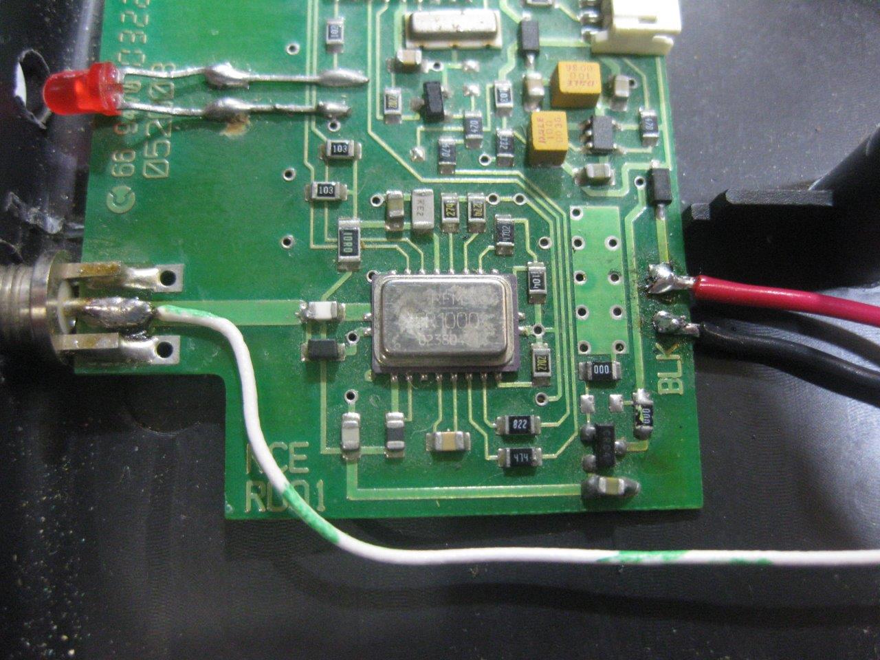
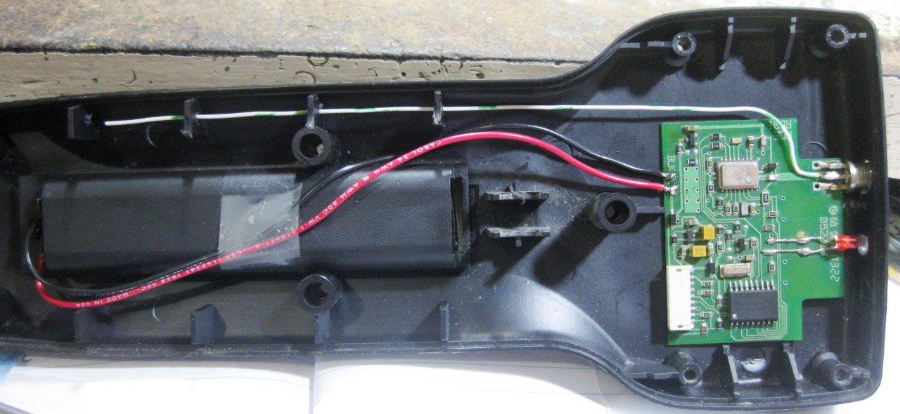
I had a problem with my Radio Procabs.
All three have issues, after been used a lot. Normal wear and tear.
First thing I noted was: Issue 1 had a intact antenna, so I used it on Issue 3's cab - One cab fixed ! then noted the setup of the pulled apart cabs. the cabs were in two halves. One cab had a intact antenna half, the other the mangled antenna half. One was ok encoder, the other the bad one. So the halves are connected by a plug. So all I had to do is swap antenna halves - Second cab fixed ! So I have a faulty encoder with a mangled antenna mount. Marcus had a fix for that. HE suggested the single wire soldered to the radio board where the antenna was. had to scrape off some green insulation to do so. This throttle now works, radio wise perfectly. With using hte encoder thumbwheel it is great, and these days I tend to use the buttons for speed rather than the thumbwheel anyhow. Tested it around te railway and at the front door. So third cab working ! This third cab still needs to sent off for repairs eventually, but for now all this has resulted in all the throttles working. |
 |
|
 |
 |
|
|
Well that's it for now. As I type this it is working bee day with Roger, and Roger is due any second - so may have more to show you soon.... |
||
Page written & maintained by David Head. dthead@hotmail.com